In heavy industry, thermal inefficiency acts as a relentless drain on profitability. Untreated exhaust and unoptimized fluid streams lead directly to severe fuel waste and escalating carbon liabilities. At the heart of this operational challenge sits the Industrial Heat Exchange Tube. It functions as the primary thermodynamic bottleneck and often represents the single point of failure inside complex shell-and-tube systems. When these components fail to perform, entire facilities suffer from decreased output and higher energy demands.
Upgrading tube specifications fundamentally transforms system performance and reliability. By optimizing materials, leveraging advanced manufacturing tolerances, and applying specialized surface coatings, plant operators directly improve overall heat transfer coefficients. You will learn how specific engineering choices mitigate severe operational risks like scaling, fouling, and dangerous pressure drops, ultimately driving measurable efficiency gains.
Key Takeaways
Optimizing heat exchange tubes can reduce thermodynamic system energy consumption by up to 20% (aligning with IEA benchmarks), primarily through waste heat recovery.
Selecting the correct manufacturing method, such as specifying a cold drawn heat exchange tube, reduces surface friction, minimizing scale buildup and the associated 25% efficiency loss from fouling.
Balancing thermal transfer with hydraulic efficiency is critical; mis-sizing tubes increases pump load (pressure drop), which can negate the financial gains of heat recovery.
For aggressive environments, advanced surface protection like a chemical high strength black varnish coating heat exchange tube extends equipment lifespan by mitigating stress corrosion cracking (SCC) without severely insulating thermal transfer.
1. Framing the Efficiency Problem: Thermal Loss vs. Hydraulic Resistance
Standard, off-the-shelf tubes often fail to balance thermal conductivity against fluid dynamics. Many procurement teams prioritize cheap initial costs. They ignore the hydraulic resistance created by poorly manufactured surfaces. Mis-sized tubes restrict fluid flow. This restriction creates severe pressure drops across the system. High pressure drops force pumps to work harder. Excessive pump energy consumption quickly erodes any financial gains achieved through heat recovery. You must balance heat transfer goals against the mechanical energy required to move the fluid.
Engineers must map the plant thermal network before specifying new equipment. We call this process pinch analysis. Pinch analysis identifies exact areas for optimal waste heat recovery. You should never guess tube parameters. You must align them strictly to actual recovery targets. Preheating boiler feed water is a prime example. Capturing exhaust heat to warm this water reduces combustion fuel needs.
To succeed, teams need to understand the core efficiency metric. The fundamental heat transfer formula is Q = U * A * ΔT_lm. Procurement and engineering must decode this equation together.
Surface Area (A): Larger areas transfer more heat. Tube length and diameter determine this variable.
Thermal Transfer Coefficient (U): Wall thickness and material conductivity directly govern the overall heat transfer rate.
Log Mean Temperature Difference (ΔT_lm): This represents the driving force between the hot and cold streams.
2. Evaluating Material and Manufacturing Specs for Process Demands
Baseline material selection dictates the operational limits of your system. Power generation cycles often operate under predictable conditions. For these standardized applications, the Low Density Carbon Steel Heat Exchange Tube provides a highly effective solution. It delivers excellent ductility and reliable structural integrity. Facilities can easily manage internal corrosion risks. Routine water treatment effectively protects these carbon steel components.
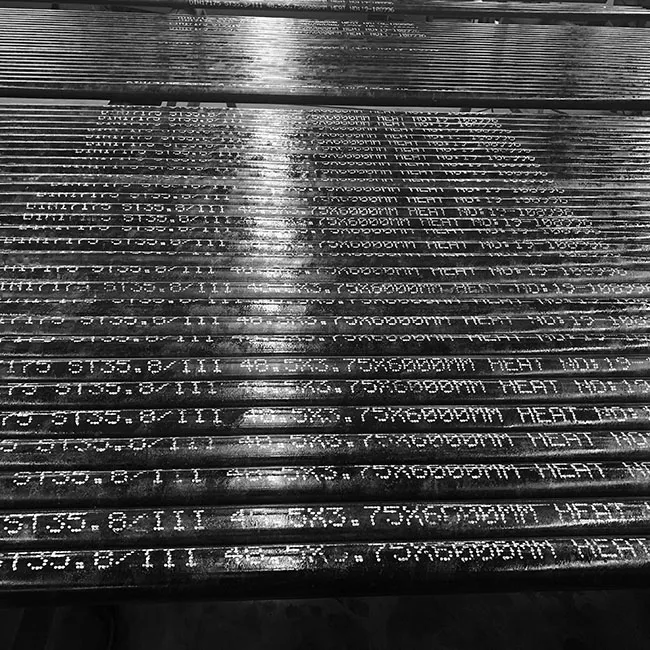
Manufacturing methods matter just as much as raw materials. Welded tubes frequently feature microscopic internal seams. These seams disrupt fluid flow and invite particulate accumulation. We contrast welded variants against the Cold Drawn Heat Exchange Tube. The cold drawing process pulls the metal through a die at room temperature. This technique yields exceptionally tight dimensional tolerances. It builds superior mechanical strength into the tube walls. Most importantly, cold drawing creates much smoother internal finishes.
These smoother internal surfaces dramatically impact operational expenses. Rough surfaces trap debris and minerals. Smooth surfaces allow particles to glide past. This dynamic directly delays the accumulation of scale and fouling. Plant managers can stretch the intervals between required mechanical or chemical cleanings. Fewer cleanings mean less downtime and higher annual production volumes.
Manufacturing Comparison Summary
Manufacturing Method | Dimensional Tolerance | Internal Surface Finish | Fouling Risk | Best Use Case |
Standard Welded | Moderate | Rough (Seam present) | High | Low-pressure, non-critical heating |
Cold Drawn | Extremely Tight | Very Smooth | Low | High-efficiency, long-cycle operations |
3. Advanced Coatings and Surface Engineering for Aggressive Media
Chemical and petrochemical environments destroy standard equipment. Bare alloys struggle heavily in these aggressive settings. Highly acidic fluids dissolve unprotected metal. Chloride-rich streams cause severe localized pitting. This pitting eventually pierces the tube wall. Cross-contamination between fluid streams occurs immediately. Plant shutdowns follow closely behind.
Advanced surface protection serves as a critical defense mechanism. Engineers increasingly specify the Chemical High Strength Black Varnish Coating Heat Exchange Tube for harsh environments. Manufacturers bake this specialized barrier directly onto the metal substrate. The dense varnish prevents active chemicals from ever reaching the vulnerable steel beneath. This barrier stops corrosion before it begins.
Some engineers hesitate to apply protective layers. They transparently address the assumption regarding thermal insulation. Coatings do add a micro-layer of resistance. However, you must evaluate the thermal versus protective trade-offs over time. Uncoated alloys foul rapidly in chemical applications. Thick mineral scale insulates far worse than any engineered coating.
Performance Degradation Chart: Coated vs. Uncoated Over 5 Years
Operational Year | Uncoated Alloy U-Value Retention | Black Varnish Coated U-Value Retention |
Year 1 | 98% | 95% (Initial coating drop) |
Year 2 | 80% (Scale forms) | 94% |
Year 3 | 65% (Heavy fouling) | 92% |
Year 4 | 50% (Pitting begins) | 90% |
Year 5 | Tube Failure Likely | 88% (Remains operational) |
This chart proves a crucial reality. Maintaining a scale-free coated surface ultimately transfers heat more efficiently over a five-year lifecycle. The varnished tube simply outlasts and outperforms the fouled, uncoated alternative.
4. Implementation Risks: Mitigating Fouling, SCC, and Mechanical Fatigue
High-demand environments expose equipment to extreme mechanical and thermal stress. Systems operating near 400°C and 40 bar push metals to their absolute limits. Thermal fatigue frequently attacks the physical structure. Rapid temperature swings cause the metal to expand and contract. This constant movement degrades material integrity. Stress corrosion cracking (SCC) remains a massive threat. It specifically targets areas under high tension. U-bend radii suffer the most from SCC failures. Operators must monitor these bends rigorously.
Understanding the economics of fouling changes maintenance strategies entirely. Plant managers should abandon arbitrary cleaning schedules. Instead, they must adopt the maintenance threshold model. Scale physically blocks heat transfer. This thermal insulation causes direct energy loss. You should schedule cleanings only when the cost of this energy loss eclipses the downtime cost of the cleaning procedure itself. Cleaning too early wastes maintenance budgets. Cleaning too late burns excessive fuel.
Facility leaders must ensure their chosen tube selection aligns perfectly alongside existing plant maintenance protocols. Compatibility prevents future headaches. Consider your current cleaning methods carefully:
High-Pressure Water Jetting: Requires durable materials able to withstand intense PSI impacts without surface flaking.
Mechanical Scraping: Demands high-hardness alloys to prevent internal scratching during brush passes.
Clean-in-Place (CIP) Washes: Needs chemical resistance to survive harsh caustic or acidic cleaning detergents.
5. Shortlisting Framework: Specifying the Right Tube for Your Plant
Selecting the optimal equipment demands a rigorous shortlisting logic. Engineering teams must vet suppliers thoroughly before placing purchase orders. Avoid vendors relying on outdated trial-and-error methods. You should advise engineers to shortlist vendors utilizing Computational Fluid Dynamics (CFD). Advanced 3D parametric modeling predicts pressure drops accurately. It simulates flow turbulence prior to physical fabrication. Catching design flaws digitally saves immense capital.
Quality assurance standards separate premium suppliers from unreliable shops. You must verify strict Non-Destructive Testing (NDT) protocols. Micro-fissures ruin entire processes. Manufacturers should implement Eddy Current Testing during production. This specific NDT method detects hidden defects inside the metal wall. It catches structural anomalies long before installation.
Procurement departments often focus entirely on CapEx. They chase the lowest initial per-meter cost. This approach guarantees long-term failure. Urge your procurement team to evaluate suppliers based on operational lifespan. High-quality systems last 20 to 30 years. Evaluate equipment based on modularity. Removable tube bundles offer immense value. When a bundle fails, operators replace the specific module easily. They avoid replacing the entire shell casing. This modular strategy drastically reduces future capital burdens.
Conclusion
An industrial heat exchange tube is never a simple commodity. It acts as an engineered asset dictating process stability, fuel consumption, and carbon footprint. When you optimize materials and coatings, the entire facility reaps the operational rewards. You protect the system from destructive fouling and crippling pressure drops.
To ensure long-term success, implement these specific actions immediately:
Force cross-functional alignment between thermal engineers, maintenance managers, and procurement teams before drafting specifications.
Map your plant thermal network using pinch analysis to identify true waste heat recovery targets.
Specify surface finishes and coatings based strictly on the chemical aggressiveness of your process fluids.
Implement the maintenance threshold model to schedule cleanings based on actual energy loss rather than calendar dates.
FAQ
Q: What are the primary factors that degrade the thermal efficiency of a heat exchange tube over time?
A: Fouling, scaling, and metallurgical degradation act as the main culprits. Minerals and particulates cling to microscopic surface imperfections. This buildup forms a thick insulating layer. It severely blocks heat transfer. Selecting a smoother cold drawn finish serves as a highly effective mitigation strategy. Smooth walls prevent debris from anchoring to the surface.
Q: How does a chemical high strength black varnish coating affect heat transfer rates?
A: The coating causes a negligible drop in baseline thermal conductivity initially. However, it delivers massive long-term efficiency retention. Bare alloys foul quickly, leading to catastrophic heat transfer loss. The varnish prevents scale buildup and stops aggressive corrosion. Over a multi-year lifecycle, the coated surface maintains far better heat transfer than an uncoated, fouled tube.
Q: When should a facility specify a low density carbon steel heat exchange tube over stainless steel or titanium?
A: Facilities should choose carbon steel for moderate temperatures and non-corrosive fluids. It perfectly fits cost-sensitive baseline utility applications. Power generation cycles using highly treated boiler water represent an ideal operational envelope. In these safe environments, expensive high-alloy alternatives offer rapidly diminishing returns.
Q: How can we test the integrity of heat exchange tubes without destructive methods?
A: Facilities rely on industry-standard Non-Destructive Testing (NDT) methods during turnarounds. Eddy Current Testing uses electromagnetic induction to detect surface and sub-surface flaws. Ultrasonic thickness measurements monitor gradual wall wear over time. These technologies identify micro-fissures and thinning safely without damaging the physical tube.


