Introduction
Why do heat systems fail early? Often, surface area is the limit. Power plants and refineries need strong heat exchange. Fin Tube designs improve heat transfer. They also save space.
In this article, you will learn how Fin Tube solutions support stable performance in industrial systems.
The Role of Fin Tube in Industrial Heat Exchange Systems
In industrial thermal systems, the Fin Tube functions as a surface-area amplifier that enables compact equipment to achieve higher heat transfer rates. When one of the working fluids—typically air or flue gas—has low thermal conductivity, simply increasing tube diameter is inefficient. Instead, extended surface geometry multiplies the external heat exchange area, accelerating convective heat dissipation without proportionally increasing system volume.
From a thermal engineering perspective, this enhancement works through three interacting mechanisms:
● Increased external surface area improves convection coefficients in gas-side heat transfer.
● Optimized fin spacing influences airflow turbulence and boundary layer disruption.
● Controlled fin geometry balances heat transfer gains against pressure drop.
In gas-to-liquid and gas-to-gas applications, these structural features allow industrial heat exchangers to maintain performance even when operating under fluctuating temperatures and varying load conditions.
Applications Across Energy and Process Industries
High-performance fin tubes are widely integrated into equipment where efficient thermal exchange determines overall system reliability. Typical industrial use cases include:
● Energy recovery systems, where exhaust gases transfer heat back into process loops to reduce energy waste.
● Boilers and economizers, where flue gas heat is recovered to improve thermoelectric efficiency.
● Condensers and air coolers, where enhanced external surface area compensates for air’s relatively low heat transfer capacity.
● Industrial heat exchangers used in petrochemical and pressure equipment environments.
The engineering objective in these scenarios is not only heat transfer enhancement, but also structural endurance under mechanical and thermal stress. This is why seamless steel tube-based Fin Tube structures are often selected for demanding sectors such as power generation and petrochemicals. Seamless construction eliminates weld seams along the pressure boundary, improving mechanical strength and resistance to internal pressure fluctuations.
Why Seamless Steel Tube-Based Fin Tube Structures Matter
In environments such as oil refining, thermoelectric plants, and industrial heating facilities, operational constraints can significantly influence thermal expectations. These include:
● Elevated temperatures combined with cyclic thermal expansion
● High-pressure steam or process fluids
● Corrosive gases or chemically active condensates
● Continuous-duty operating cycles
A seamless steel tube base provides consistent wall thickness and structural uniformity, which enhances dimensional stability during thermal cycling. When combined with engineered fin structures, the resulting Fin Tube system delivers both mechanical durability and sustained heat transfer performance across long service intervals.
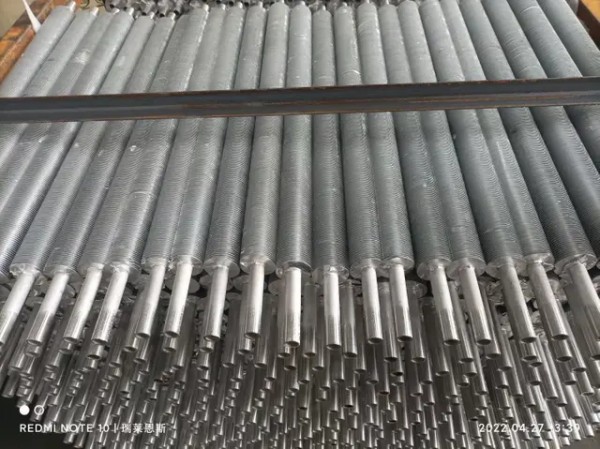
Fin Tube Manufacturing Process for Heat Exchangers
The manufacturing of a Fin Tube for industrial heat exchangers is a coordinated process involving material selection, fin attachment methodology, and dimensional control. Each stage influences long-term thermal efficiency and structural reliability.
Base Tube Material Selection
The foundation of a Fin Tube begins with selecting the appropriate seamless steel tube. For many heat exchanger applications, seamless carbon steel tubes compliant with ASTM/ASME A/SA179 are commonly specified due to their balance of thermal conductivity and mechanical strength. These tubes are particularly suitable for moderate to high-pressure environments in thermoelectric and industrial heating systems.
In more aggressive conditions—such as corrosion-sensitive petrochemical processes—stainless steel and alloy seamless tubes are selected to improve resistance to chemical exposure and oxidation. Material grade selection must account for:
● Operating temperature range
● Internal pressure requirements
● Corrosion exposure
● Compatibility with downstream equipment
Precision seamless steel tube manufacturing plays a central role here. Tight dimensional tolerances ensure concentricity, uniform wall thickness, and surface integrity, which directly affect heat exchanger assembly and long-term structural performance.
Major Fin Attachment Technologies
The method used to bond fins to the base tube determines both thermal continuity and mechanical stability. Several primary configurations are applied depending on industrial temperature and operating conditions:
● Extruded Fin Tube configurations, where fins are formed integrally to enhance mechanical bonding and reduce thermal resistance.
● Welded Fin Tube structures, providing strong structural attachment suitable for high-temperature and high-pressure applications.
● Embedded (G-type) Fin Tube designs, where fins are mechanically locked into grooves for improved retention under vibration.
● Roll-formed bonding methods, often used in stainless steel fin structures to ensure consistent contact between fin and tube.
● Hot-rolling metallurgical bonding processes, which promote improved heat transfer continuity through enhanced contact integrity.
Each method balances manufacturing complexity, bonding strength, and service condition suitability. The appropriate choice depends on operating environment rather than solely on cost considerations.
Dimensional and Structural Control in Production
Dimensional precision is critical in Fin Tube production because small geometric variations can significantly affect airflow and heat exchange behavior. Industrial manufacturing therefore includes strict control over:
● Fin density and spacing, tailored to optimize heat exchanger design requirements.
● Outer diameter range (5MM–114.3MM OD) and wall thickness range (0.5–20MM WT) to match pressure equipment specifications.
● Structural stability under thermal cycling and pressure fluctuations.
The following table summarizes key dimensional control parameters in seamless steel-based Fin Tube manufacturing:
Parameter | Typical Industrial Range | Functional Impact |
Outer Diameter | 5MM–114.3MM | Determines compatibility with heat exchanger shell or coil design |
Wall Thickness | 0.5–20MM | Influences pressure tolerance and mechanical strength |
Fin Density | Customizable | Affects heat transfer rate and airflow resistance |
Pressure Testing | Hydrostatic testing per standard | Verifies structural integrity before deployment |
Alignment with recognized industrial standards and pressure testing protocols ensures that each Fin Tube meets the structural and safety expectations of power plants, petrochemical installations, and HVAC systems.
Through coordinated material selection, attachment technology, and dimensional precision, the Fin Tube manufacturing process supports stable performance across diverse industrial heat transfer applications.
Fin Tube Design for Power Plant Boilers
Power generation systems impose some of the most demanding operating conditions on a Fin Tube assembly. In boiler economizers, air preheaters, and heat recovery sections, the tube bundle must withstand sustained exposure to high-temperature flue gases while maintaining stable thermal efficiency. Design decisions at this level directly affect fuel utilization, steam generation efficiency, and long-term equipment reliability.
High-Temperature and Thermal Cycling Demands
In boiler systems and power generation heat recovery units, Fin Tube components operate under repeated thermal expansion and contraction cycles. These cyclic loads can introduce mechanical fatigue if the base tube and fin bonding method are not structurally aligned with temperature gradients.

Key thermal stresses include:
● Rapid temperature rise during startup and shutdown phases
● Continuous exposure to elevated flue gas temperatures
● Differential expansion between fin material and base tube
To address these challenges, the design must balance heat transfer enhancement with mechanical endurance. Seamless steel tube foundations provide uniform wall thickness and eliminate longitudinal weld seams along the pressure boundary, reducing stress concentration under cyclic thermal loading. When combined with appropriate fin attachment methods, the assembly maintains dimensional stability across long service intervals.
Structural Requirements for Reliability
Boiler and thermoelectric environments require high-strength structural performance in addition to thermal efficiency. Fin Tube configurations used in these systems are typically designed around pressure equipment standards, ensuring compatibility with steam generation and high-pressure heat exchange circuits.
Critical structural considerations include:
● Resistance to internal pressure in economizers and superheater sections
● Structural bonding integrity between fin and tube under thermal shock
● Compatibility with soot-blowing and cleaning operations
The following table summarizes the relationship between design factors and operational reliability in power plant environments:
Design Element | Functional Requirement | Operational Impact |
Seamless steel base tube | Uniform wall strength | Improved resistance to internal pressure |
High-integrity fin bonding | Reduced thermal contact resistance | Stable heat recovery efficiency |
Controlled fin geometry | Balanced airflow and fouling resistance | Consistent flue gas heat exchange |
A properly engineered Fin Tube system in boiler applications is therefore not defined solely by heat transfer capacity, but by its ability to maintain structural reliability under extreme thermomechanical conditions.
Performance Under Fouling Conditions
Flue gas environments often contain ash, particulate matter, and combustion residues that accumulate on fin surfaces. Over time, fouling can reduce heat transfer efficiency and increase pressure drop across the heat exchanger.
Design strategies to mitigate fouling effects include:
● Optimized fin spacing to allow effective gas flow
● Structural rigidity to tolerate soot-blowing maintenance
● Material selection resistant to surface degradation
In long-term operation, the durability of the fin attachment and base tube becomes critical. Mechanical deformation or corrosion at bonding interfaces can accelerate performance decline. Therefore, Fin Tube systems used in power generation must be evaluated not only for peak thermal performance, but for sustained efficiency under fouling-prone operating conditions.
Welded Fin Tube Performance in Corrosive Environments
Refineries and petrochemical plants expose heat exchange equipment to chemically aggressive media and elevated pressures. In these settings, the structural and metallurgical characteristics of a Welded Fin Tube become central to long-term reliability.
Refinery and Petrochemical Operating Conditions
Oil refining and chemical processing systems commonly involve:
● Sulfur-containing gases and acidic condensates
● High-temperature hydrocarbon streams
● Pressurized heat recovery and process heat exchangers
Such conditions require Fin Tube systems capable of resisting corrosion while maintaining mechanical strength. Unlike moderate HVAC environments, refinery applications demand enhanced bonding stability and material compatibility to prevent premature failure at the fin-to-tube interface.
Material and Welding Strategy
Material selection plays a decisive role in corrosive environments. Stainless steel grades such as 304, 316, and 321 are frequently specified due to their improved resistance to oxidation and chemical attack. The choice depends on exposure severity, temperature range, and process chemistry.
Bonding strategy is equally critical. Metallurgical bonding achieved through hot-rolling or welded fin attachment methods ensures minimal thermal contact resistance and robust structural connection. Proper welding procedures reduce micro-gaps that could trap corrosive agents and initiate localized degradation.
Where applicable, compliance with standards such as ASTM B-432 and ASTM B338-2010 ensures dimensional and material consistency for industrial heat exchanger applications. These standards help define acceptable mechanical properties and quality verification parameters.
Long-Term Durability Considerations
Corrosion rate control is essential in chemical and alkaline environments. Even small material losses can alter wall thickness and compromise pressure resistance over time. For this reason, Fin Tube systems in petrochemical facilities must demonstrate:
● Stable corrosion resistance under specified pH conditions
● Pressure tolerance compatible with industrial boiler and process heat exchanger requirements
● Structural bonding strength that withstands prolonged chemical exposure
Hydrostatic pressure testing prior to shipment provides an additional safeguard by verifying tube integrity under controlled overpressure conditions. This step ensures that each Fin Tube assembly meets structural expectations before integration into refinery or chemical process systems.
Custom Fin Tube Solutions for HVAC Systems
In HVAC and water heating applications, Fin Tube design priorities shift from extreme thermal resistance to efficiency optimization, compactness, and installation flexibility. While operating temperatures are typically lower than in power or refinery environments, design precision remains essential for stable heat exchange performance.
Fin Tube configurations for commercial HVAC heating coils and air coolers are engineered to balance airflow resistance with effective surface area. Lightweight structural combinations reduce system load, while compact geometries facilitate integration into constrained mechanical rooms or rooftop units.
Application-Specific Configurations
Different HVAC and water treatment scenarios require tailored tube lengths and corrosion protection strategies. For example:
● A 4m Steel Fin Tube may be applied in residential or industrial water heating systems, reducing connection points and improving installation efficiency.
● A 1m Anti-corrosion Fin Tube can support municipal water supply, wastewater treatment, or heating circuits where space constraints and corrosion exposure are relevant considerations.
These configurations are designed to improve heat transfer continuity while maintaining compatibility with system pressure and temperature requirements.
Customization Parameters for Diverse HVAC Needs
HVAC and refrigeration systems often demand flexibility in geometric and material specifications. Customizable parameters include:
● Fin densities ranging from 19 to 40 fins per inch
● Variable outer diameters and wall thicknesses
● Material grades selected for humidity and moderate chemical exposure
The table below summarizes key design flexibility elements in HVAC-oriented Fin Tube solutions:
Parameter | Customization Range | Functional Benefit |
Fin Density | 19–40 FPI | Optimizes airflow and heat exchange balance |
Tube Length | 1m / 4m options | Adapts to installation constraints |
Material Grade | Carbon steel / Stainless steel | Matches corrosion and durability requirements |
By aligning geometric configuration, material grade, and installation context, Custom Fin Tube solutions for HVAC systems support efficient heating, cooling, and water treatment operations while maintaining structural integrity over extended service periods.
Conclusion
Fin Tube manufacturing shapes heat transfer and system durability. Seamless steel expertise supports stable performance in power, refinery, and HVAC systems. Right fin design must match conditions. Material choice matters.
Suzhou Baoxin Precision Mechanical Co.,Ltd. provides precision Fin Tube solutions. Their products enhance efficiency, strength, and long-term value.
FAQ
Q: What factors affect Fin Tube performance in power plants?
A: Fin Tube performance depends on fin geometry, base material strength, and bonding method under high temperature and thermal cycling conditions.
Q: How is a Fin Tube manufactured for industrial heat exchangers?
A: A Fin Tube is produced by attaching fins through extrusion, welding, or embedding to a seamless base tube for stable heat transfer.
Q: Why is welded Fin Tube preferred in refineries?
A: Welded Fin Tube designs provide stronger bonding and better resistance to corrosion and pressure in petrochemical environments.
Q: How should Fin Tube be selected for HVAC systems?
A: Fin Tube selection should match airflow, operating temperature, corrosion exposure, and dimensional requirements of the HVAC application.


